What is reverse power flow?
Reverse power flow is associated with electricity substations, and specifically with the transformers in substations. Historically, power flow in the electricity network has always been ‘top to bottom’ – from the big generators (top) down through the voltages to the end users (bottom). When power is flowing from the lower voltage side of a transformer to the higher voltage side (i.e. from bottom to top) this is defined as reverse power flow.
Article by Pete Aston – acknowledged expert in networks
Pete joined Roadnight Taylor from Western Power Distribution, the UK’s largest DNO, where he was Primary System Design Manager. He led a team of sixty responsible for all connections and reinforcement of the extra high voltage network and oversight of the roll out of active network management across all four of WPD’s licence areas.
1st April, 2022

History of the grid
Historically, power flow in the electricity network has always been ‘top down’. Big generators, like coal, gas and nuclear power plants, would feed hundreds or thousands of MW into the transmission network (which operates at 275kV or 400kV).
The transmission network would then transport this power long distances from the generators to demand centres. There would then be off-take points on the transmission network, usually called Grid Supply Points (GSPs), where there would be transformers to change the power from 400kV down to 132kV.
From a GSP, the power would then be distributed out to increasingly smaller substations, where there were other sets of transformers to reduce the voltage, with the power going out to the end users. So the power would come from the top (the big generators), down through the voltages to the bottom (the end users).
At each substation the power flowed from the high voltage side to the low voltage side, and this is defined as forward power flow.
Figure 1 below shows a substation with two 90MVA transformers and a demand of 20MVA, with a forward power flow of 20MVA.

Figure 1: Two 90MVA transformers and a demand of 20MVA, with a forward power flow of 20MVA.
The rise of embedded generation
Embedded generators deployed over the last two decades have typically been less than 100MW and so have been too small to connect to the transmission network. These generators, such as wind farms and solar farms, have been connected at distribution network voltages, such as 132kV, 33kV and 11kV. And these connections change the power flow, as shown in the examples below.
In this scenario (figure 2), a 15MW generator is connected to the substation. It reduces the power flowing through the transformers to only 5MVA, but the power is still in the forward direction.

Figure 2: Two 90MVA transformers, a demand of 20MVA, and a 15MW generator.
In this next scenario (figure 3) , a 25MW generator is connected to the substation. It is big enough to supply all the power for the 20MW demand and to push 5MW back into the grid. When power is flowing from the lower voltage side of the transformer to the higher voltage side (i.e. going from bottom to top) this is defined as reverse power flow.
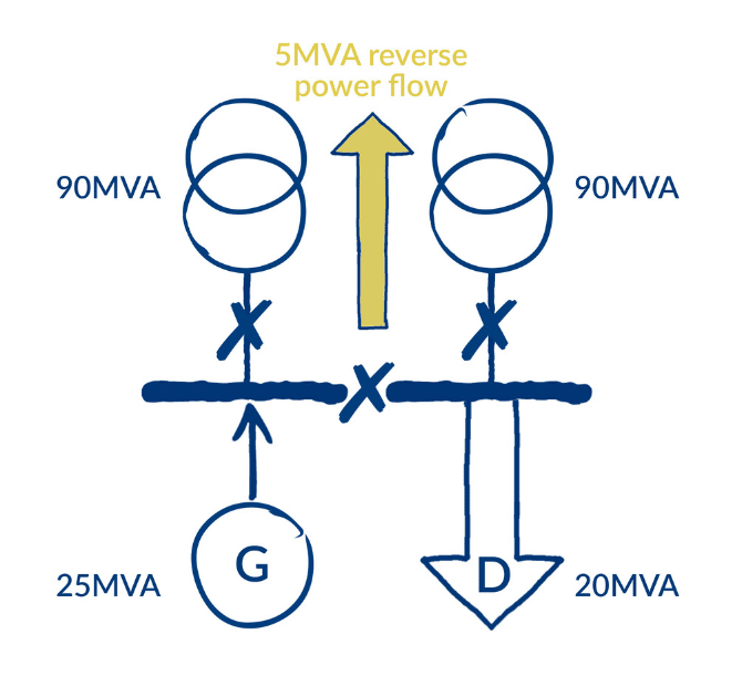
Figure 3: Two 90MVA transformers, a demand of 20MVA, and a 25MW generator showing reverse power flow.
What issues does reverse power flow cause?
Reverse power flow in and of itself is not necessarily a problem for the transformer, as it is basically a lump of iron with copper windings, and the copper itself doesn’t mind which direction the power goes, as long as it’s not too high.
But there are other bits of kit and other network parameters that reverse power flow can cause a problem with. The following list describes some of the main issues.
- The rating of the transformers is the first thing to look at (for example the 90MVA rating in the examples above). If the reverse power flow is greater than the rating of one transformer (as the network companies will assume one is switched out when making their assessment), then the generator can’t connect, or needs to be smaller, or the network needs to be upgraded.
- The tap changers on the transformers don’t always have the same rating in the reverse direction as in the forward direction. This is particularly true for older models. So for example, instead of having a rating of 90MVA in the reverse direction, it could potentially have a rating of only 45MVA.
- Automatic Voltage Control (AVC) relays measure the voltage on the low voltage side of the substation and trigger the tap changers to go up or down to maintain a steady voltage. These were historically designed to control the voltage in the forward direction and some of them don’t work in the reverse direction. These can usually be changed without changing the transformers, and customers would be charged for their replacement.
- Directional Overcurrent (often abbreviated as DOC) protection relays are often included in substations to look at power flowing in the reverse direction through a transformer, to detect faults on the high voltage side of the transformer and to trip off the circuit breaker. However, these relays often can’t differentiate between normal level load current and fault current, and so could spuriously trip if there was too much reverse power flow. As such, these relays often need to be changed when a generator causes reverse power flow.
- Reverse power flow through a transformer results in the voltage on the high voltage side of the transformer increasing. Sometimes this can increase to levels that are too high for the network equipment to cope with, or go over the statutory voltage for other customers. In this instance, the network company would need to work out a network reinforcement scheme to help keep the voltage down to acceptable levels.
Contact us
Roadnight Taylor can help customers understand if there are likely to be reverse power flow issues as a result of the connection of a generator to a substation. To find out more call us on 01993 830571 or send us a message via our contact form.