What are transformers and how do they work?
On a power network, transformers are most frequently found in network substations and generating sites. Their main job is to change the voltage from one part of the network to another.
Article by Pete Aston – acknowledged expert in networks
Pete joined Roadnight Taylor from Western Power Distribution, the UK’s largest DNO, where he was Primary System Design Manager. He led a team of sixty responsible for all connections and reinforcement of the extra high voltage network and oversight of the roll out of active network management across all four of WPD’s licence areas.
1st April, 2022

Electrical voltage is a bit like gas pressure. High pressure is good because it makes the gas flow fast, but to contain high pressure your pipes need to be very strong, which gets expensive. So, in a gas system, really high pressure is used to transport high quantities of gas a long way across the country, whereas low pressure is used for the smaller and cheaper pipes coming into your house.
The same is true with electricity. Expensive high voltage lines take high power long distances across the country, but cheaper low voltage cables are used to take low power into your house. To switch between the high and low voltages, we use a transformer.
When electricity flows through a wire, it produces an electromagnetic field. If the wire is coiled up, the magnetic field becomes very concentrated. Air isn’t good at passing magnetic fields, but iron is great at doing it. If you wind your coil of wire around some iron, most of the magnetic field tends to stay within the iron.
Coil windings explained
Imagine you have a rectangle of steel, like in figure 1 below. Now wind two coils of wire around it, one on one side of the rectangle, one on the other. Electricity comes through the wires on one side, turns into a magnetic field through the iron, which causes electricity to flow in the other wire. An awesome and very useful phenomenon of physics!
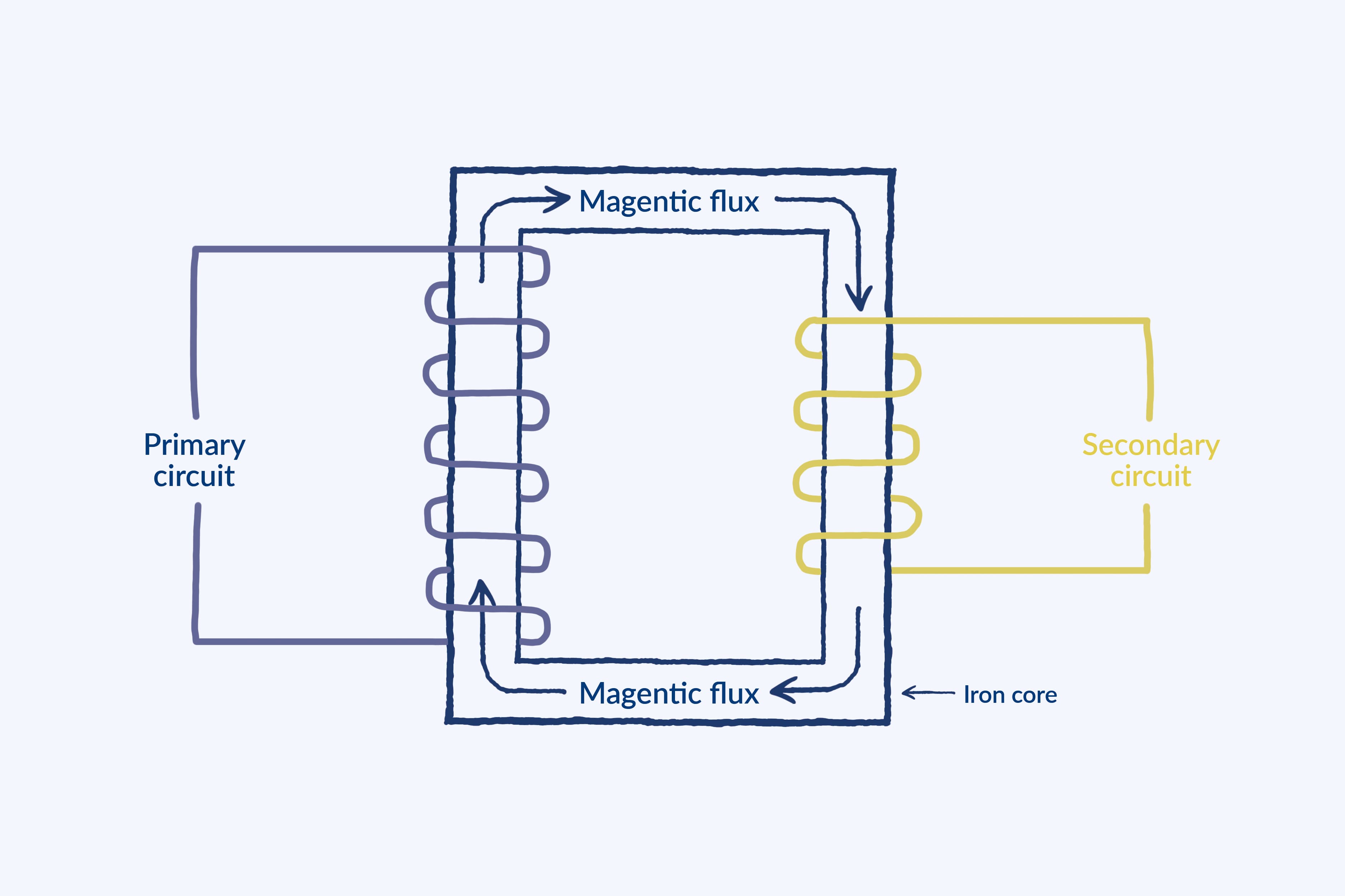
Figure 1. A simplified transformer with a primary and secondary winding.
This diagram shows a standard transformer for simplicity. Super-grid transformers are auto-transformers and are slightly different to what is shown, but the diagram gives the general idea.
The main winding (on the left in figure 1) is at the higher voltage and is where the power is coming from. This is normally called the ‘primary’ winding. The winding that takes the power on somewhere else, at a lower voltage (on the right figure 1) is normally called the ‘secondary’ winding.
The great trick with this, that makes it useful as a transformer, is that if you change the number of windings on the secondary side, it changes the voltage. If the secondary winding has a greater number of turns than the primary winding, the voltage goes up on the secondary side. And if the secondary winding has fewer turns than the primary side, then the voltage on the secondary side goes down. And this is how a transformer works!
Some transformers have a third winding, a tertiary winding, which provide opportunities for what are called tertiary connections onto National Grid’s transmission system.
Contact us
Roadnight Taylor can help you with tertiary connections for your project. To find out more call us on 01993 830571 or send us a message via our contact form.